Full Bleed Maps with ArcMap
Download the mxd (9.3) used in this article here
Incorporating full bleed into your map design will instantly improve the professionalism of your products. Full bleed refers to the ink of the map going to the edge of the paper.
To achieve this effect, the map is design and produced on a page size slightly larger than the finished trimmed page size. For a map that will be trimmed to 24” x 34” the layout and design is done on a 25” x 35” page. The extra space compensates for trim marks as well as some extra room for the map art itself. The art will extend beyond the 24” x 34” envelope. Trim marks will be placed at a slight offset of the 24” x 34” envelope and later guide trimming the map to 24” x 34”. Once the map is printed (with no scaling) the paper will be cut in a cookie cutter fashion.
This effect is a bit more seamless to achieve in a workflow that incorporates Adobe Illustrator or InDesign but if your workflow is constrained to ESRI products this is a useful trick to know. Accomplishing this in ArcMap will give you the background experience needed to achieve a full bleed product in any workflow.
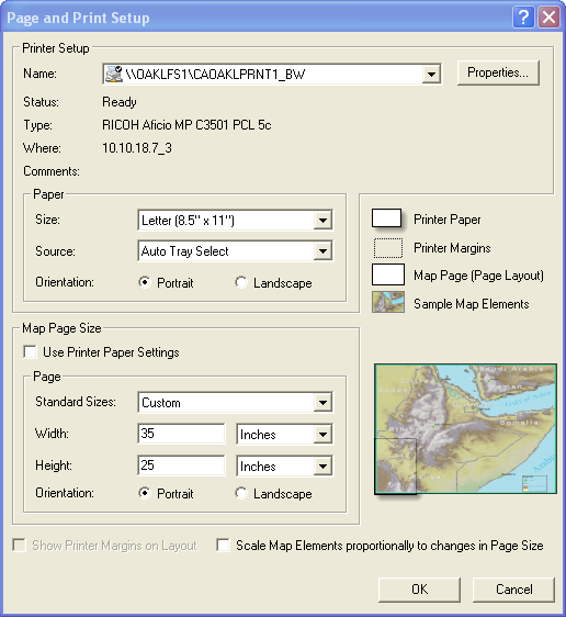
To begin, start a new ArcMap session. I’ll design a map that will be trimmed to 24” x 34” and I usually start by setting the page size even before adding any data. Go to File>Page and Print Setup…
In the Page and Print Setup dialogue I usually ignore the Printer Setup area because I prefer to export maps to PDF and print from the PDF print dialogue. You can definitely set up the printer and print from here it’s just not my preference. To set up the map, focus on the Map Page Size area. First uncheck Use Printer Paper Settings, then set the width to 35 inches and the height to 25 inches. Remember, our final trimmed size will be 34” x 24” and we need the art to extend past those dimensions so that after we trim the map the ink will travel all the way to the edge of the page. This is the bleed area, the extra paper area that contains art but will be trimmed away to achieve the full bleed effect. The extra inch accommodates the bleed area and allows us to add crop marks or trimming guides. Generally the bleed area should be 1/8th of an inch in ArcMap it is easier to set up guides and draw crop marks in 1/10th of an inch increments since these are the increments you can add guides to the map on. Our goal is to add slightly offset crop marks and bleed area in the extra 0.5” space we’ve created on each edge by setting the map page size to 35”x25”.
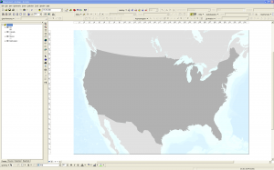
After setting up the page layout, add your data and set your extent and scale and view the map in Layout View. In the example map, I have the Continental US, Canada, Mexico and Natural Earth Bathymetry displayed in the US National Atlas Equal Area projection.
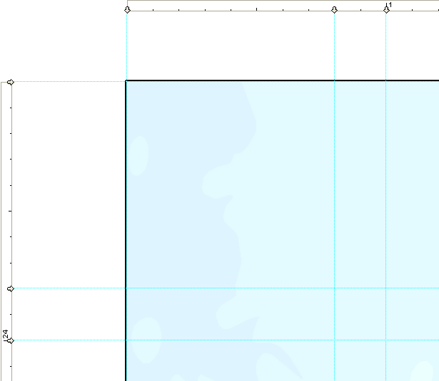
Now, with the layout zoom tool or by holding control and drawing a box by clicking your mouse wheel button, zoom to the top left corner of the map. Zoom in so that you can see about 2 inches square of the upper left portion of the map.
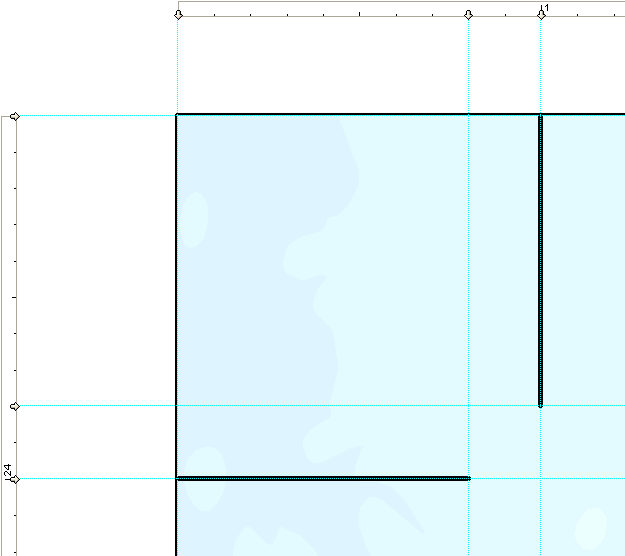
Set guides, by clicking on the ruler area, on the top edge at 0.0”, 0.8” and 1”. Also set guides on the left edge at 25”, 24.2” and 24”.
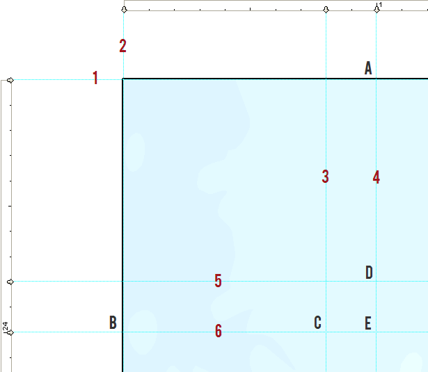
In the image above, I have labelled a few parts of the guide setup where the letters are guide intersections and the numbers are the guides and they can be defined as follows:
Guides
1 Top edge of total page layout (25”)
2 Left Edge of total page layout (0”)
3 Left boundary of bleed area (0.8”)
4 Left edge of trimmed page (1”)
5 Top boundary of bleed area (24.2”)
6 Top edge of trimmed page (24”)
Guide Intersections
A Top end of crop mark
B Left end of crop mark
C Right end of crop mark
D Bottom end of crop mark
E Top-Left edge of trimmed page
Next I’ll start drawing the crop marks for the map. Using the New Line Tool in the Draw toolbar, draw a line from B to C in the above image.
This can be a little tricky because of the snapping tolerances when using guides, if you mess up just start over. Also draw a line from A to D.
Notice that the crop marks do not extend to the edge of the trimmed page (label E in the previous image). The reason for this is that once the page is trimmed properly, no remnant of the crop mark will be left.
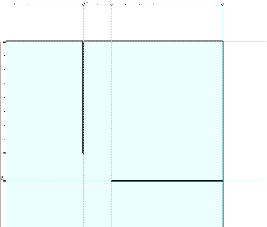
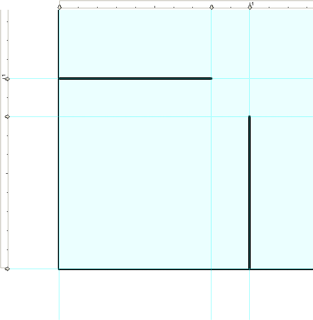
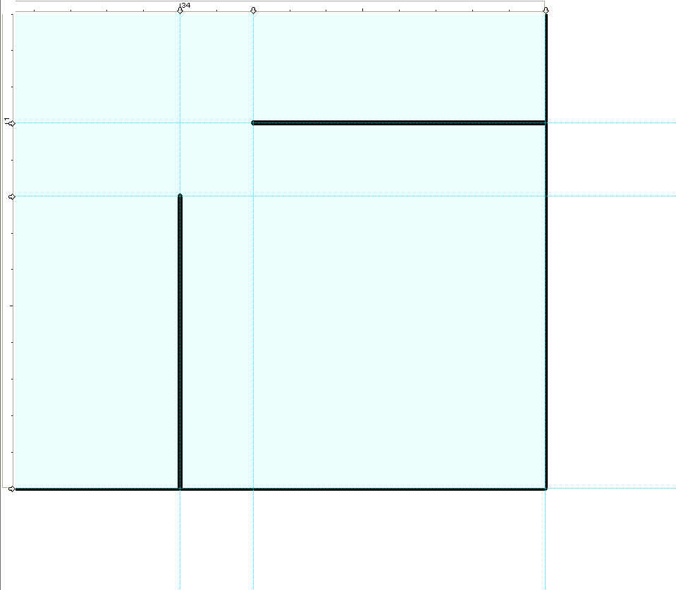
Repeat for the top right, bottom left and bottom right corners of the page.
Now the bleed are a crop marks are set and the map can be exported or printed. Remember not to place important art outside of the trim boundary or it will be cut off when the map is trimmed. Also, if your preference is to export to a PDF and print from the PDF menu remember not to scale the page, so that your trimmed size will remain correct along with the scale of the map itself.
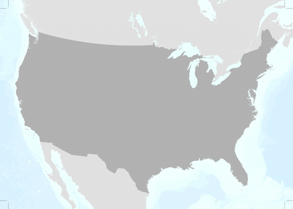
Here is the finished map with crop marks at 35” x 25”.
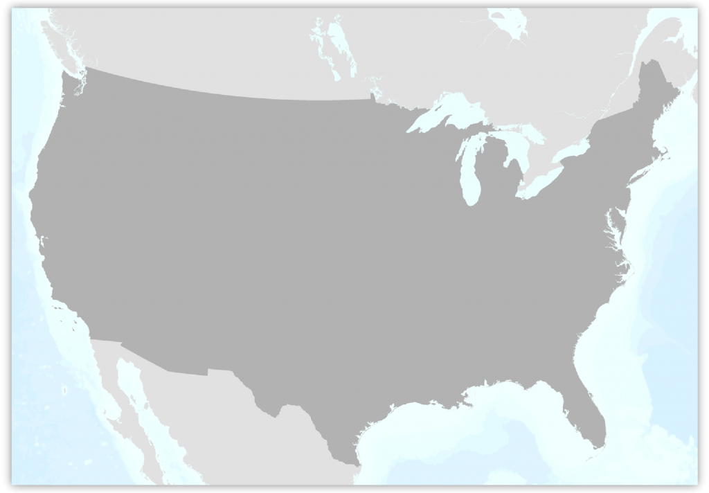
Add this is what it might look like trimmed.

