Leadered Symbols in ArcMap
This is a follow up to the “Custom Marker Symbols in ArcMap” article. So you’ve learned how to incorporate custom enhanced metafile graphics as marker symbols in ArcMap – now I’ll show you a trick to put those symbols on the end of a leader. This is useful in cases where marker symbols will be bunched or a marker might obstruct another feature – similar to leadering a label.
First, fire up ArcMap and load a point layer (this is also effective for line features and possibly polygons).
Open the properties of the point layer by double clicking the layer name in the table of contents or by right clicking and choosing properties.
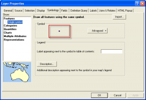
First, let’s change the feature symbol to a clean black dot. This will be on the feature end of the leader (the item that the symbol is pointing to). Go to the symbology tab in the properties window and hit the symbol to change the properties.
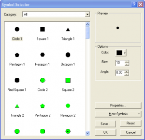
Choose the “Cicle 1” symbol and enter 10 for the symbol size and hit okay. Then hit apply in the Layer Properties menu.
Now, we will build the leadered symbol. This leadered symbol is actually a label, one with no text color and a symbol background.
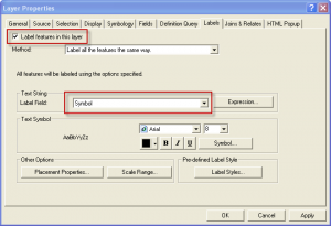
Go the the Labels tab in the Layer Properties menu and check the “Label features in this layer” check box at the upper left. Choose the Label Field as well. Try to choose a field that has short values or calculate a new field with only a couple characters for the sake of this symbol. Keep in mind that some placement properties will be associated with a label that you cannot actually see. You can control the placement of the leadered symbol by visualizing this ghost label. For instance, if you calculate a field with the value “11211” and set your labeling properties with a force split at the character ‘2’ then you can overlap the area of a square symbol fairly well and control overlap and proximity when auto labeling features.
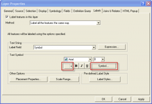
Next, in the Labels tab change the text color to ‘no color’ then hit the ‘Symbol….” button.
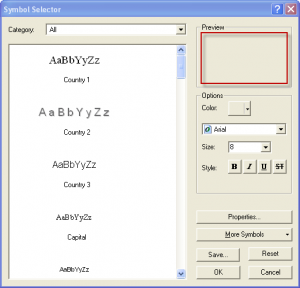
This will bring you to the Symbol Selector menu, the first step in a maze of menus that we need to get through to achieve the leadered symbol. Double click the symbol in the preview window.
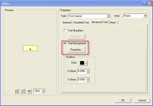
This will bring up the Editor window, go to the Advanced Text tab, check the Text Background checkbox and click on the properties button.
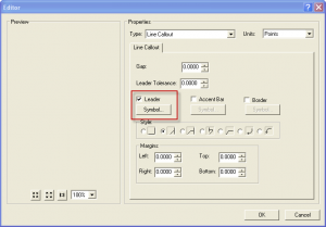
A new Editor window will appear. Change the following settings: Gap: 0, Leader Tolerance: 0, Set all Margins to 0, Uncheck Accent Bar and Border. Check Leader and click on the Symbol button.
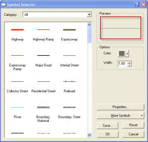
Upon hitting the Symbol button a new symbol selector menu will appear, double click the symbol in the preview window.
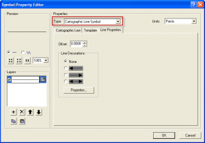
In the Symbol Property Editor change the type to Cartographic Line Symbol then go to the Line Properties Tab.
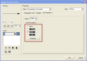
Choose the line with the arrowhead on the right side and click Properties.
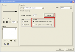
Finally we are in the menu where we can put a custom symbol on the end of our leader. In the Line Decoration Editor menu, hit the Symbol Button.
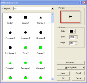
In the Symbol Selector Window that appears, double click the symbol in the preview pane.
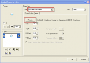
Another Symbol Property Editor menu will appear, change the Type to Picture Marker Symbol and select an emf file for the line decoration symbol.
Hit OK on the many open windows until you get back to the Layer Properties menu. Do not hit cancel on any menu or you will lose your work. You should now see your symbol on the end of a line in the Text Symbol preview pane.
Hit OK to view the results.
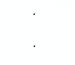
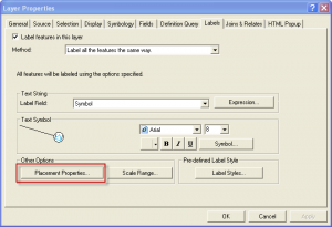
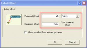
Notice that the leader does not have allow enough room for the symbol to draw and the result is not quite what we expected. Go back into the layer properties and the labels tab. We will now push the offset of the label far enough for the symbol to show. In the Labels tab, click on the Placement Properties button.
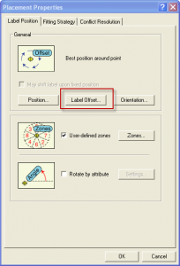
In the Placement properties window, click Label Offset.
Enter the values shown. Preferred Offset – 25 points and Maximum Offset – 500%.
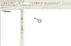
Hit OK to return to the map and to see the leadered symbol.




12 Comments
dianne
January 24, 2012This works great but what happens when I need my point feature symbolized for two different things – underground swtich and overhead switch? How do I distinguish them to show a different symbol for each type of switch?????
Brian
January 24, 2012Hello Dianne, you would choose to symbolize based on categories. In the first “layer properties” window above, you would choose categories instead of single symbol. You would then choose a field to symbolize based on the underground/overhead attribute and apply a different leadered symbol to each. To save time in the future you could also save a generic leadered symbol, apply the saved symbol and simply navigate through the style menus to choose a different symbol on the end of the leader.
Brian
May 23, 2013http://forums.arcgis.com/threads/85128-Picture-Labels-with-leader-line-from-point-without-annotation?p=300994#top
I am having issues with the offset matching the picture when it is not positioned on the east. The second thread of my post shows a picture of my problem. Any suggestions?
Thanks for this post. Prior I was trying to convert bmp to glyph font to solve this, which would’ve been difficult on the graphic design side of things.
Brian
May 28, 2013Hi Brian,
I had the same problem in the mapping featured in this post’s image. There’s not too much you can do. I played around with the end cap types in the symbology of the leader lines I used. Another thing you can do is calc a field to offset certain features only to the right or only to the left and offset the marker symbol accordingly so that you don’t get the overhang. Bottom line is that it’s a little tricky and takes trial and error.
There may be a more graceful solution but that’s what I’ve got off the top of my head.
Brian
Dominic Lacroix
February 7, 2014Hi Brian,
Do you need the Maplex extension to do this? I’m using ArcMap 10.0 with an ArcInfo license and I was able to get almost to the very last step of your instructions, but my Label Placement window looks very different from yours with much less options. I’m stuck with the little black circles with a tiny tail and my leadered symbol doesn’t draw. Is there any other way of setting parameters that will allow the symbol to show if label offset options are not available?
Thanks
Brian
May 5, 2014I believe so but at 10.1 maplex is available at every license level. You should still be able to adjust the leader tolerance of the text symbol to a lower value in order to have the leader symbol draw – multiple label classes with different settings may be the key to this issue.
Kevin Lecocq
May 5, 2014First of all, great post! I never tried to set the leader symbol as an arrow, then change the marker to an EMF picture, very good idea! Thanks a lot.
However, my case is a bit more complicated: I have an not square EMF picture and the data frame is rotated by a certain angle. Then, I applied the EMF as a marker symbol with an angle of the negative of the map angle and I get my EMF not centred on the end of the line callout. I could use X, Y offsets to center if on the end, but when Maplex change the label position, the X, Y offsets are no longer good.
Do you have a solution for this problem?
Thanks.
Brian
May 5, 2014You may be able to avoid using a calculated angle by experimenting with the setting to rotate labels with data frame rotation (in Labeling Options). And yes, the x, y offset is out the window in this situation. You may be able to get away with changing the end type of the leader line – also experiment with the gap value in the line callout settings. I think a square end cap to your leader line and the right amount of gap may work out for you. There is a lot of strange behavior when rotating the data frame – my general rule of thumb is to stick with rotating the data frame with only positive integers, which seems to help in some cases.
Norrin
December 30, 2014This is a great tutorial. Is there a way to have it where there is a regular arrowhead at the point location and the symbol on the other end. If I try it with the double arrow head it replaces both with the symbol.
thanks
chris
May 31, 2017Thank you. Works well. have to play with offset. Odd that ‘never remove’ is not prioritized over label offset as many placements are removed due to label on label conflict. solution is to amp up offset of line but this creates line criss-cross mayhem, so dense point datasets still need manual editing. yet this is a great solution for many applications. bravo
ryanne
August 30, 2017Thank you. I would like to put the label text in the circle (based off attributes). Do you know how to do this?
Van
March 11, 2020I have the same question as Ryanne…. I need an attribute as part of the symbol.